

Categories
- Case & News (50)
- Blog (604)
A twin shaft concrete mixer is a key piece of equipment for mixing concrete. Its structural design focuses on efficiently mixing materials (cement, sand, gravel, water, etc.) and consists of the following core components:
1. Mixing Mechanism
The mixing mechanism is the core of material mixing and directly determines mixing efficiency and concrete homogeneity. It includes:
– Mixing Shafts: Typically composed of two parallel, long shafts (hence the name “twin-shaft”), these shafts are made of high-strength steel and are responsible for transmitting power and mounting the mixing blades. Bearings secure the shafts at both ends to ensure rotational stability.
– Mixing Blades: Arranged helically along the shaft, these blades are typically made of wear-resistant cast iron or high-strength alloys. They achieve uniform mixing by impacting, shearing, and tumbling the material. The blade angle can be adjusted based on the material’s characteristics.
– Mixing Arms: The component connecting the shaft and the mixing blades must be sufficiently rigid to withstand the impact forces of mixing. In some designs, the mixing arms are removable for easy blade replacement.
2. Transmission System
Responsible for transmitting power to the agitator shaft, driving its rotation, it primarily includes:
– Motor: Provides the power source, typically a three-phase asynchronous motor. Power varies depending on the concrete mixer model (capacity), ranging from several kilowatts to tens of kilowatts.
– Reducer: Due to the high output speed of the motor, a reducer is required to reduce the speed and increase the torque. Common types include gear reducers and cycloidal pinwheel reducers. This ensures the agitator shaft rotates at an appropriate speed (usually 10-30 rpm).
– Coupling: Component that connects the motor to the reducer, and the reducer to the agitator shaft. It transmits torque and compensates for minor misalignments during installation. Common types include elastic couplings (to reduce vibration transmission) and rigid couplings.
– Chain/Belt Drive: Some small agitators use chains or V-belts to connect the motor and reducer. This simple structure offers lower cost, but the transmission efficiency is slightly lower than that of a gear drive.
3. Feed System
This system is used to feed concrete raw materials (cement, sand, gravel, water, additives, etc.) into the mixing drum in appropriate proportions. It includes:
– Hopper: A container for aggregates such as sand and gravel, typically equipped with a hopper gate (controlled by a pneumatic or hydraulic cylinder). A lifting mechanism (such as a winch) lifts the hopper to the mixing drum inlet for discharge.
– Cement Metering Device: This is typically a screw conveyor coupled with a metering scale, which delivers a set amount of cement from the cement silo into the mixing drum to ensure accurate mixing ratios.
– Water and Additive Piping: Water is pumped from a water tank by a pump and fed into the mixing drum after flow control by a flow meter. Liquid additives (such as water reducers) are simultaneously injected through a dedicated pump and pipeline.
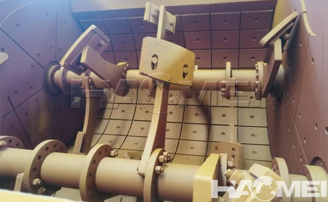
4. Mixing Drum (Shell)
The mixing chamber for materials is typically a horizontal trough structure, closed at both ends. It forms the mixing chamber with the agitator shaft and impellers. The inner wall is often lined with wear-resistant plates (such as high-manganese steel) to reduce wear on the drum wall and extend its service life. A discharge port is located at the bottom of the mixing drum, and the concrete is discharged via a discharge door.
5. Discharge System
This is used to discharge the mixed concrete from the mixing drum. It primarily includes:
– Discharge door: Located at the bottom or end of the mixing drum, it is typically fan-shaped or rectangular, made of wear-resistant material, and fits snugly against the drum to prevent leakage.
– Drive: This is the mechanism that controls the opening and closing of the discharge door. Small mixers often use a manual rocker, while medium-sized and larger mixers often use pneumatic (cylinder) or hydraulic (hydraulic) drives, enabling fast and smooth opening and closing. The discharge door opening is adjustable to control the discharge speed.
6. Frame and Support Structure
This supports the weight of the entire equipment, including the mixing mechanism, drive system, and feed system. It is typically constructed of welded steel sections (such as I-beams and channel steel) and must possess sufficient strength and stability to ensure no significant vibration or deformation during operation. Some frames have anchor bolt holes at the bottom for securing the equipment to the foundation.
7. Control System
Enables automated operation and parameter control. It consists of an electrical control cabinet, sensors, and an operating console:
– Control Cabinet: Contains electrical components such as contactors, relays, and a PLC (Programmable Logic Controller) to control the start and stop times of motors, pumps, valves, and other equipment.
– Operating Console: Equipped with buttons, knobs, and a display screen, the operator can set parameters such as mixing time and raw material ratios, and monitor equipment operating status (such as motor current and discharge door position) in real time.
– Sensors: These include weight sensors (for raw material measurement), liquid level sensors (for monitoring tank levels), and proximity switches (for detecting hopper position). They provide signal feedback to the control system to ensure accurate automated operation.
8. Auxiliary Systems
– Lubrication System: Lubricates moving parts such as the agitator shaft bearings and reducer. Typically, a manual grease gun or automatic lubrication pump is used. Regular lubrication is required to reduce wear.
– Dust Removal: Vacuum cleaners or bag filters are installed at dust-prone locations, such as the cement feed inlet, to reduce dust pollution and improve the working environment. Safety devices, such as overload protection (automatic shutdown when the motor is overloaded), limit switches (stopping the hopper when it reaches its limit), and emergency stop buttons, ensure the safety of the equipment and operators.
These components work together to achieve automatic feeding, uniform mixing, precise metering, and efficient unloading of concrete raw materials. They are widely used in construction, precast component plants and other applications. While different models (such as the JS series twin-shaft mixer) may have slight structural differences, their core components are generally the same.